A Clock that affects every Timeline within its collider by multiplying its time scale with that of their observed clock.
AreaClock
Updated: 2018-09-06
Area clocks can be moved, scaled and rotated at runtime. They can even stack and combine their effects!
Properties
ClockBlend innerBlend { get; set; } = MultiplicativeDetermines how the clock combines its time scale with that of the timelines within.
| Value | Description |
|---|---|
| Multiplicative | The area clock's time scale is multiplied with that of the timelines. |
| Additive | The area clock's time scale is added to that of the timelines. |
In most cases, multiplicative blend will yield the expected results. However, additive blend becomes extremely useful to affect your timelines when they have a time scale of 0.
AreaClockMode mode { get; set; }Determines how objects should behave when progressing within the area clock.
| Value | Description |
|---|---|
| Instant | Objects that enter the clock are instantly affected by its full time scale, without any smoothing. |
| PointToEdge | Objects that enter the clock are progressively affected by its time scale, depending on a A / B ratio where:
|
| DistanceFromEntry | Objects that enter the clock are progressively affected by its time scale, depending on a A / B where:
|
See the Notes section below for diagrams and more explanations for these modes.
AnimationCurve curve { get; set; }The curve of the area clock. This value is only used for the PointToEdge and DistanceFromEntry modes.
| Mode | ||
|---|---|---|
| Axis | PointToEdge | DistanceFromEntry |
| Y | Indicates a multiplier of the clock's time scale, from 1 to -1. | |
| X | 0 is at the | 1 is at entry; |
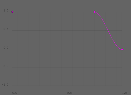
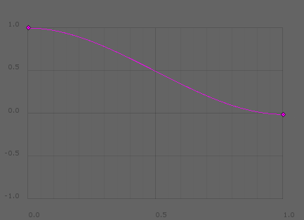
A good use for this curve is to dampen an area clock's effect to make it seem more natural. Think of the curve's left being the centermost part of the clock, and right being the edge. Common damping curves for both modes are illustrated below.
Vector center { get; set; }The center of the area clock. This value is only used for the PointToEdge mode.
float padding { get; set; }The padding of the area clock. This value is only used for the DistanceFromEntry mode.
Methods
void Release(Timeline timeline)Releases the specified timeline from the clock's effects.
void ReleaseAll()Releases all timelines within the clock.
If the timeline enters the clock after having been released, it will be captured again. To configure which area clocks capture which timelines, use Unity's collision matrix.
void CacheComponents()The components used by the area clock are cached for performance optimization. If you add or remove the Collider on the GameObject, you need to call this method to update the area clock accordingly.
Notes
This section contains diagrams that help understand how the PointToEdge and DistanceFromEntry modes function. For simplicity, 2D area clocks are represented, however the same concepts and calculations apply to 3D area clocks.
Point To Edge
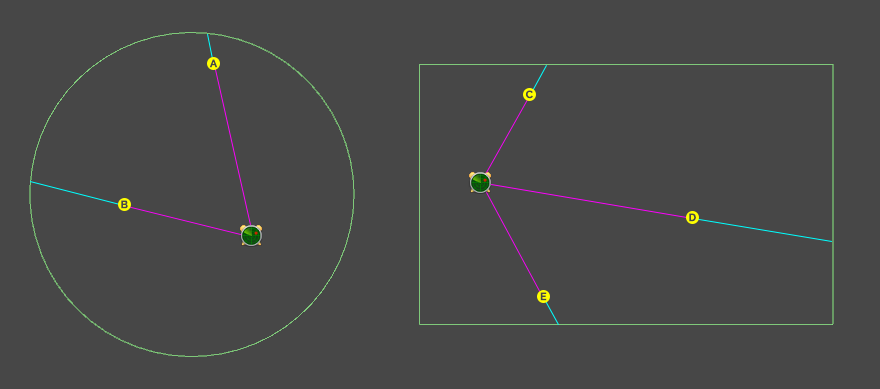
In the point to edge mode, the X value of the curve property is calculated by the distance of the object from center to the edge of the area clock.
In the above diagram, this represents the following ratio:
x = Magenta line / ( Cyan line + Magenta line )
For example, A and E would have an x value of about 0.8, while B and D would have an x value of about 0.6. In the unlikely event that an object was placed at the exact center of the clock, its x value would be 0.
Distance From Entry
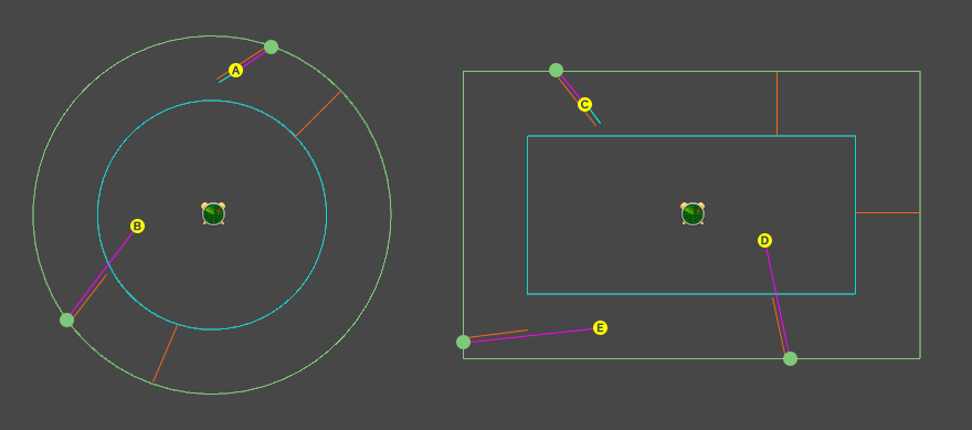
In the distance from entry mode, the X value of the curve property is calculated by the distance of the object from its entry point relative to the value of padding.
In the above diagram, this represents the following ratio:
x = Cyan line / Orange line
For example, A and C would have an x value of about 0.25, while B, D and E would have an x value of 0, because they went over the maximum distance.
The inset cyan collider has no real impact on the calculation. It is merely a helper that lets you visualize how big the value of padding looks while in the editor. Indeed, unless objects enter perfectly ortogonally to the collider's edge, their max distance will not be at the edge of the inset cyan collider.
You can display the cyan and magenta lines for both modes in scene view by enabling Timekeeper.debug.
Previous
LocalClock
A Clock that only affects a Timeline attached to the same GameObject.
Next
Timeline
A component that combines timing measurements from an observed LocalClock or GlobalClock and any AreaClock within which it is.
Was this article helpful?
Be the first to vote!